


This started from a simple discussion on the lounge, where Dean asked about PCB layouts. Dean was asking on how he can go to identify what parts of an amplifier or a DAC, and what function do they do. I think we all have asked such questions before, and while I’m typing the reply to Dean’s question, I find myself writing something close to a full length article. So I thought, I’d make it a full article on the website.
I’m gonna start with saying that all Amplifiers and DACs consist of mainly two parts: Power supply (PSU) section, and the actual amplifier/DAC section. Fancier units may also have a separate section for user interface controls that covers anything from volume adjustments, input selections, display LCD, and other functions on the user interface.
All electronic devices need a PSU section to supply clean power to the actual amplifier or DAC circuit. The power supply circuit can be on a separate enclosure (i.e on the big amps like the Beta22. Check out the Beta22 article for internal shots.), or in a form of a wallwart, or joined together in one enclosure as the amplifying or DAC circuit. Normally if you see an amplifier or a DAC internal shots with a toroidal travo inside the enclosure, then that means that the power supply is housed on that circuit. A PSU circuit can be very simple, consisting of travo, diode, capacitors, and regulator chips, to something as complex as the Sigma22 power supply (check out the Beta22 amplifier photo down below). Simpler doesn’t always mean poorer performance, and more complex better, but the goal of a good PSU section is to supply a clean and consistent power to the circuit to be powered. Some amplifiers run on single rail power supply, and some on dual rail power supply. The requirement is normally specified on the design of the amplifier circuit.
After the PSU circuit comes the actual amplifier, or DAC circuit. There really is no bottom line rule to this, as the design of amplifier or DAC circuits varies significantly from one model to the next. Amplifier circuits are quite varied, and the layout will vary as much as the design and topology of the amplifier. Vacuum tube circuits, solid state circuits, and hybrid (vacuum tube & solid state mixed design) circuits. In the realm of solid state circuits, opamp-based (or chip-based) circuits are normally simpler, as the the opamp is designed to replace quite an array of parts that would otherwise be required in an all-discrete circuit. You’ll later see how the amplifier circuit of the M-Stage (opamp based) is much simpler than that of the Beta22 circuit (all discrete).
Now, let’s take a look at some real circuits to try to see what’s going on.
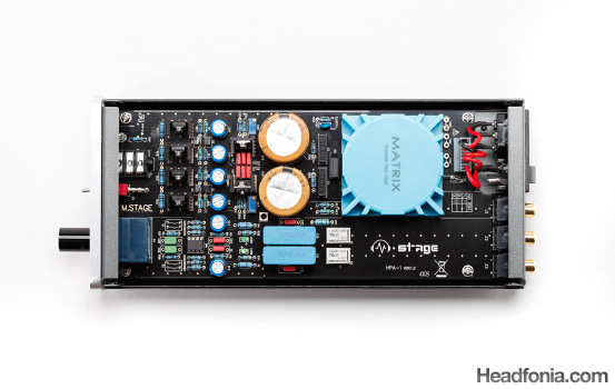
The Matrix M-Stage
Here is the Matrix M-Stage layout that has the PSU section also enclosed in the same enclosure. Notice how the toroidal comes with its own enclosure (blue color) that’s designed to suppress noise level on the electronic circuit. Left of the toroid are two big capacitors (the gold/silver colored circles) which should be the power supply capacitors, and next to it are two black small U-shaped heatsinksfor the power supply regulators (along with some red color wima capacitors for the regulator). Those are the power supply circuit. Next to the then you have the amplifier circuit to the left of the power supply circuit. You have four black U-shaped heatsinks that house the power transistors for the amplifier circuit, and the opamp is placed below it, on the right side of the blue box–the potentiometer that controls the volume.
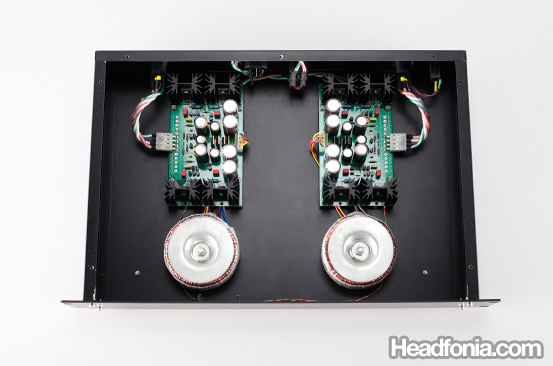
On the other hand, this is the Beta22 amplifier, and it comes with two separate enclosures for the Amp section and the PSU section. The amplifier section is far more complex and more serious than the M-Stage. It comes with four separate PCBs to handle a fully balanced stereo signal: L-, L+, R-, R+. On the center is a volume control, mounted on a shaft that links it to the volume control knob. This is an all discrete design, hence you will find no chips anywhere in the PCB, either on the amplifier circuit or the PSU circuit. An all discrete design normally takes up more space than a chip/opamp design, but you get better sound quality in return for the space disadvantage. This is why good amps are usually big in size.

The Beta22 - Amplifier Section.
On the back panel (top section in this view), are signal input connectors, as well as power input connectors (remember that the PSU is on a different enclosure).
Like the amplifier section, the PSU section of the Beta22 is all discrete, and the complexity of the circuit is far higher than a typical PSU with a chip regulator. There are two identical power supply unit with two travos for supplying power independently to the L and the R channel of the amplifier.
The Beta22 - PSU Section (aka Sigma22).
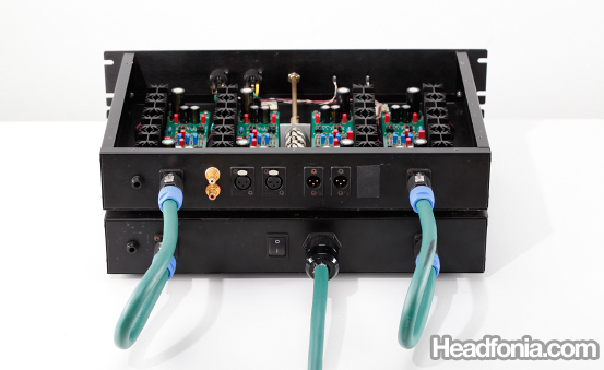
Rear view of the Beta22 shows two green cables that send power from the PSU to the Amplifier section.


Dean_jet
I was glad you used the Dacmagic as i own one and opened it up for a look but could not work out where bits were lol
Is it sad of me to really like the internal look of the M-stage, its really neat and tidy compared to others!
Mike
You have the DacMagic too? That thing sound good doesn't it? I personally love the symmetrical layout of the Beta22 amp. 🙂
Dean_jet
Really good read!
Mike
Thanks Dean!
Dean_jet
Yeah i do like the sound but i have not really hurd any other dac accept the internal dac of my reciever. I recently bought a AudioQuest Ciniman USB cable for it which was good!
On the M-stage, the 2 big psu capasitors, does having few big ones or lots of smaller ones like on the dacmagic have any benefits?
Mike
I think that's mostly due to space constraints and layout purposes. It shouldn't matter if you have several small ones or one big one.
Dean_jet
Well I was thinking, why use lots of small ones if you could just use a few big ones, gives you more space for other things and must be cheaper?
The Beta22 amp is a hefty size, I’m surprised they made such a big box!
So I understand that separating everything is better but i don’t get why? Is it to do with interference?
I no how to solder so i was thinking of doing some building to help me learn, like a DIY amp or something that i have read about, any suggestions?
I know its off topic but I just read your first impressions of the HM-602 looks really good!
Mike
Well often a certain brand capacitor only comes at a certain size, and another reason that is also important is also the bigger a capacitor in diameter is, the taller it often gets. So, everything gets calculated into the enclosure design.
Separating the box can be for two reasons. One, to get a smaller footprint. I.e: if the Beta22 was cramped into one box, it would be one really big box. The second reason often is to place the travo away from the amp circuitry, since the travo will induce a hum when placed close to the amp.
The Cmoy amp is always a good place to start learning. You can start by reading tangensoft's cmoy tutorial (google tangensoft cmoy). Pyschaudio is making Cmoy PCBs and a bunch of us is ordering the PCB. But shipping cost can be far more expensive, and besides for learning purpose it'll probably be better to use a plain board.
The HM-602 is looking very good!
Dean_jet
Just took a quick look, very interesting, looks like a great read. Thank you.
wwenze
Two big capacitors “in the main PSU”, one for +V and one for -V
Multiple smaller ones near each individual components for “faster local power supply”, also +V and -V where applicable
Mike
Thanks wwenze. People like you should write full length articles. 🙂
David
About big vs smaller cap array:
Some designer choose to use of multiple smaller capacitors to get a smaller ESR (internal resistance).
1 unit of 10,000uF cap will be most likely would have higher ESR then 10 x 1000uF capacitor.
Think power supply like an amplifier supplying power to the load, but in this case is the circuit as the load. The lower the power supply impedance (here the cap array usually fronting) the more robust and control that the PSU have over the circuit.
Mike
Thanks David. Got anything else to share? I'm sure I missed a LOT of things on that article!
wwenze
10 x 1000uF caps also take up more physical and PCB space than a 10000uF cap from the same series, while the rated impedance (usually at 100kHz) of a 1000uF cap is roughly 3 to 5 times that of a 10000uF cap from the same series.
Then the extra PCB trace length required to connect the capacitors together negates the benefit of lower impedance for the same capacitance.
And one can mount probably two to four 10000uF caps in the same physical and PCB space required for 10 x 1000uF caps.
Mike
Thanks wwenze for the addition!
Dean_jet
What is the IC Socket/chip for on the dacmagic next to the dsp chip, I can’t get the white sticker off it!
Mike
Dean, the files are low resolution, and I can’t read it as well.
Jonathan
Hello. I can't see the pics on page 1 🙁
Mike
I will get it fixed immediately!
Mike
Everything is fixed now. Thanks for letting me know about this problem. 🙂
Jonathan
Wooohooo.. Thanks a bunch.
Qusp
i dont think you can be so general with a dac, most high quality dacs will have power supply components scattered liberally throughout and particularly local to each section, the dac chip itself will have several for what is usually several different required voltages, the clock definitely needs local regulation as do the spdif or usb input receivers . in a good layout this will be separated further into digital and analogue sections, often each with its own ground plane.
Anonymous
Thanks, Qusp.
Qusp
no problem, its a complex subject, these techniques are most often just used for dacs, its rare, but not unheard of for amplifiers. for dacs the regulators and associated decoupling caps should be as close to the supply pins as possible. some companies and indeed diyers take this to the extreme.
Anonymous
Yes, you’re right. Anyway the article is just meant as an introductory article.