


Braiding a cable
Wether we’re going to make an un-balanced or balanced cable we’re going to need 4 wires. So we’ll need to cut those wires to the length we’re aiming for and add 10%. So a 120 cm (aprox 4 ft) cable means four wires á 132 cm. In my case I’ve cut up 8 wires á 132 cm since I’ll be doing a little special move. I like to cover 2 wires with nylon TechFlex. The best size for 24-26AWG wire is 3/32″ wide TechFlex. It can be a real pain to get especially a long set of wires through all the sleeving. But I like the look and feel of it. Similar to Q-Cables and Toxic-Cables so called “French Silk”. It ain’t silk we’re using, so it can be a bit microphonic. It’s your choice since it’s your cable. Do what you wish. Be warned the 4 x 2 x 24 AWG and sleeving yealds a quite hefty diameter. You’ll be needing connectors that accept such a wide diameter.
Next comes the braiding. Before we start discussing braiding it might be a good precaution to add something so you can identify the wires Either you know how to use a multimeter and you can skip it altogether, or you stick different colors of electrical tape on both ends of each wire to identify them later. Or a hefty array of permanent markers (presuming you’re not using black insulated wire)
A quad-braid which will suit most needs (even if we want to use 8 wires) and it comes with a special technique. It can be a bit tricky to understand at first but once you understand each wires “role” that is UP, DOWN, LEFT, RIGHT it’ll come naturally. Generally speaking you’ll be making the same move in two dimensions. Horizontal (LEFT & RIGHT) and vertical (UP & DOWN). This is probably the most hideous image I’ve created the last few years, but I think it’ll contain more information than popping 5-6 pictures. So bear with me. 🙂
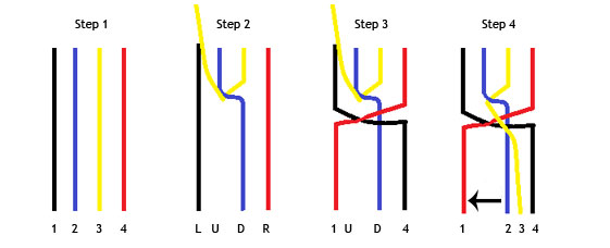
So we have four wire for starters. Well name them 1 2 3 4 for now. The first move is creating the UP and DOWN. So move the 2/Blue to the right over 3/Yellow and 3/Yellow to the left and up (away from you in 3D). We have now created our basic 4 wires the LEFT, UP, DOWN, RIGHT. Take R/Red to the left over L/Black and move L/Black to the right. All of the latter mentioned happens above the D/Blue. Now take the U/Yellow and move it down over the whole shebang and keep it to the right, so it comes over D/Blue and move the latter to the left. Well go figure, now we have a new setup of 1 2 3 4 but the earlier 1 and 4 has switched seats, the same for 2 and 3. We’ve created a 3D “knot”. Don’t pull it too tight. And by moving 2/Blue up away from us we’re actually at step 2. L = Red, U = Blue, D = Yellow and R = Black. Now keep repeating it. As many times it’ll be needed.
When you feel that you have about 25-30 cm’s left of wire end the braiding process and start spinning two of the wires around each other. Fasten the three ends of the cable with something suitable. Some thin heatshrink tubing will do the trick the best. Don’t worry about it being ugly.However, make sure that the braids are about equally tight. It’s not uncommon the braids closer to you (the ones at the end of the process) are tighter than the first ones. But be sure to check that your two headphone ends are equally long. Note all the “be sure to….”? It’s takes a couple of cables to learn by doing the beginners mistakes. As everything else in life, practice makes perfect. So maybe invest in some extra connectors and some cheap wire at first. Even if you’re a cable-believer. You don’t want to waste 99,9999999999% first harvest einsteinium-coated silver-wire. 😉
Soldering the ends
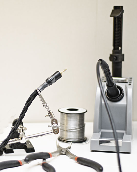
Let’s start by stripping the wires at all ends. 0,5 cm or 1/5 inch will do just fine. You want to strip just as much as you will need to solder the connection. Strip too much and you risk creating shorts. A snipped nose plierss will come in handy so you won’t “pull” the wire to strongly thus affecting our soft and flexible braid. So the pliersss in your left hand (unless you’re a lefty) and the wire stripper in the right hand. And get to work.
Now that all the ends are stripped. We’ll learn a technique that will come VERY handy in the future if you’re going to extend your DIYing. Tinning wire. Basically what we’ll be doing is heating up the stripped wire end with our soldering iron and trying to coat the wire with solder. Making it much easier to solder to a fixed metal object (e.g. a pin on a connector) without having to worry about adding solder later. So tin the wires. Some wires are quite happy to blend with the solder and others no so easy. But hopefully you’ll get the hang of it.
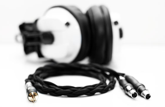
So our wire is prepared now bring forth the connectors. Remember earlier when we discussed single-ended and balanced signals? Well in short. No matter what we choose to terminate with at the amp end, at the headphone end we’ll be connecting the L+ to the positive end of the left headphone connector and L- to the negative. The right channel… well you get the picture. In my case with the Audez’e cable for my T50RP Paradox, since it’s a 4-pin mini-XLR. Pin 2 & 3 are + and 1 & 4 – (or ground with a single-ended cable). So heat up the tinned end and when you think that the pin has made contact with the wire, try to hold them still while the solder cools down. If they solder together you might add some extra solder to increase the strength of the connection. Depending on how your headphone is wired you might need to connect 1 & 4 and 2 & 3 together, with either solder or a wire-bridge or something. Be creative.
So… Now we’ve soldered the connectors on the headphone end. Now it’s time to move on to the amp end. Either you use your multimeter to identify the different wires or you did your homework and marked them prior to braiding. But if you want to start soldering the amp end you better know which wire goes where. I recommend using 1/4″ TRS or 4-pin XLR if you’re a novice. 1/8″ TRS can be quite tricky to work with and unintentional shorts can happen.
Either way. Solder. Oh… And be sure to get the barrel on the cable before soldering. You only make that mistake once. 😉 Once the cable is fully soldered. You might be thinking “let’s add some heatshrink and we’re done?”. Not quite yet. Test it first. The best way to do that can be argued about. I usually use a O2-amp. I’m not that fond of it, in the case of total havok. Start with one side at a time. If it’s cool, then try both at the same time. If you shorted something you’ll hear it. In that case, go back, desolder the suspicious parts and/or use some electrical tape to isolate wires that might be touching with the barrel on.
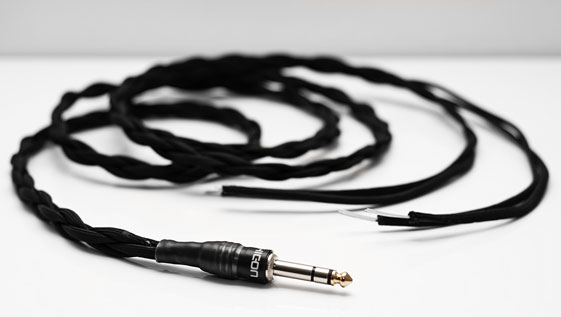
If everything looks and sounds good. Add some heat shrink. There is no right and wrong here. My tip is to use transparent heat shrink as the “final” layer. Don’t warm too much with the heat gun (if it doesn’t shrink anymore after 5-10 seconds. It wont shrink anymore. 😉 I’ve actually melted the isolating plastic inside a 1/8″ TRS once).
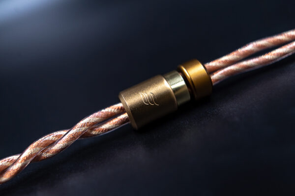
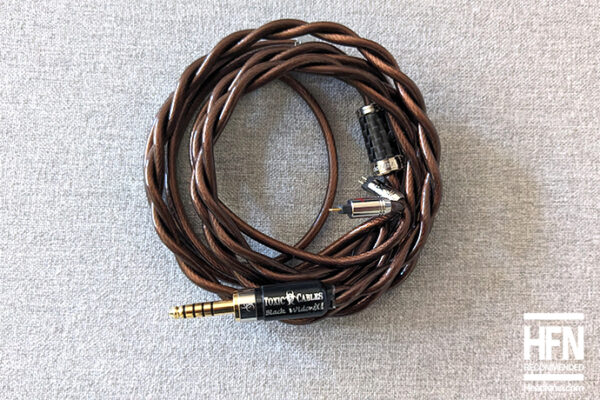
When you’re finished it might look something like this. If it doesn’t well… You’ll get there… Eventually. Keep DIYing and Fight the Man.
thethirty3rd
This is great, thanks Valentin!
Gonna try making some cables in the summer, your guide will be one of my few references 🙂
Valentin
Sweet! Hope they turn out mighty fine. As mentioned earlier. Buy more connectors and cheap cable and experiment! It’s the only way 😉
L.
Awesome guide V! great job
Valentin
Thx mate!
Dave Ulrich
Nice!
John123John
OMG. Totally wish I had this when I got into DIY like 2 years ago.
I did alot of googling and emailing cable makers to get info. I had a very hard time matching heatshrinks to wire diameteres for some reason.. very annoying.
Another type of wire I’d recommend is silver plated copper (SPC) wrapped in teflon found for cheap(er) on ebay. Saves time from fitting a wire inside a little tube especially when running more than like 4 ft. also make sure its the soft nylon techflex and not that hard one which is super microphonic.
“Oh… And be sure to get the barrel on the cable before soldering. You only make that mistake once. ” cant call yourself a DIYer if this hasnt happened to you lol!
some advice for noobs (like me), its a learning experience and it gets easier/faster over time 🙂 (once you learn how to litz braid which referring back to the diagram over and over) +1 on the colored tape.
anyways great article/guide val!
makes me want to get back into DIY ^^
Nick Tam
Honestly the SQ of SPC has been debated… personally I’d prefer just doing a hybrid silver/copper cable if I just wanted both the sonic characteristics of silver and copper
Rūdolfs Putniņš
Great article, Val! Good to see that someone promotes fighting the Man with a soldering rod!
One thing tho- cables electrically can be described by three parameters- resistance, capacitance and inductance. And technically its not the wire that “sounds” the way it sounds- it’s the output stage of a device coping with a load that is presented by the cable. Ideally an output stage must maintain the same characteristics in all reasonable loads, but unfortunately this can be far from truth. Hence the cable may or may not change the sound of a system depending on the system. A good circuit should not have any audible change.
Good luck with your builds! I hope this isn’t the last article about DIY!
Valentin
You are very correct in the above mentioned! Thx for expanding it a bit to the readers! 🙂
More articles will most likely follow. 🙂
Nick Tam
Next up: 8 wire and 16 wire round plait!
Valentin
I like ’em. But to be honest i prefer doing round 4×2 instead. I find them more flexible and less intrusive.
Plus… It’s a lot easier to do and requires less time. But they sure can be fancy! 🙂
Nick Tam
Good guide!
A note on wire: the gauge of the wire and the size of the TRS connector you are going to use is ultimately what makes it easier to work with. Also, you may want to expand on the use of single core wire versus stranded core wire as I find this a massive difference to work with if I’m making higher strand count cables.
Valentin
Thx for the input!
I’ll add some about the above to the next one!
/V
kongmw
Nice write-up! I wish there was one like this when I first started making my own cables. Also, this soldering iron of yours looks really fancy! lol
Valentin
I’ll pop some pics to show how to make a really sweet 3,5 mm to 3,5 mm. Always needed. Not costly either. Tune in later. 🙂
/V
Sasmit
Nice article Valentin!….I hope to do this one day…How do you find the time to balance medicine and your various hobbies?
L.
I nag alot
Valentin
True dat! 😉
Nahh.. In short. I’ve cut down on most hobbies in later years. I used to be all over the place. Now I only have time for hi-fi/head-fi; work/research and my family.
It’s good to be realistic. I like popping pics, but not enough to invest in a new rig with more strobes, a full-size sensor-camera and new prime lenses etc. Since I know that I could take much better pics if I had better gear… well.. Let’s just say it limits my photography to everyday pics and headfonia-stuff.
Writing. I’ve cut down on most forum-life to the strict necessary. Not many posts on head-fi/changstar/head-case etc. And that’s why I’m not so prolific in the DISQUS here on headfonia (I try to write articles instead).
Work. Well… I’m diverting myself more and more toward Oto-rhino-laryngology and later to audiology. Hopefully be able to work with developing hearing aids and such in the future.
Working out. Well, let’s face it. Can’t lift weights as I used to. You only have that testosterone-period in your life once. Plus… Vanity. Nahh. Just trying to stay healthy, and you don’t have to train much to attain that. 😉
Family. The most important part. If I feel that I neglect them. Well, then time to cut down on the stuff above.
Cheers guys!
V
Sasmit
This makes me appreciate your great articles even more….cheers and best of luck for otorhinolaryngology
Jerry
Very useful article, this sort of information might seem like very basic stuff for many of the more advanced headphiles out there but a lot of people learn these basics wrong, so an article about making DIY cables certainly is useful, to newbies and veterans alike.
Since what you describe in this article is basically making an interconnect (ie. a cable with plugs on both ends), it might also be a good idea to have another article with tips on how to recable an actual headphone ie. what mistakes to watch out for, how to use a multimeter, how to create a DIY strain-relief etc.) After all, relatively few headphones these days have detachable cables. Furthermore, most headphone manufacturers do not put warranty on the cable, so simply recabling a headphone does not void waranty, while modifying the headphone to add a DIY socket certainly would.
Szwety
Hey great article! One question about the number of wires… Maybe I’m reading it wrong but why did you need to cut up 8 wires for a 4 wire braid? Did I miss something?
Valentin
I use 2 x 24 AWG as one, which actually equates to 1 x 21 AWG.
That’s why I use 8 wires. However I do a Quad-braid since I find flat 8-braids to be highly time-wasting and non-ergonomic.
Cheers!
V
John123John
So with the specific headphone cable you made, you have 4 separate Nylon Techflex wires/cables so you would have 2 wires per Techflex totaling to 8 wires. Are the wires in the Techflex just twisted pair?
So you just braided the Techflexes..
What is the difference between the fully insulated cables such as moon audio or cardas vs braided cables such as Toxic and BTG?
Making a cable – not rocket science but there are so many types of braids, wires, insulation, sheathing, etc… its easy to make it more complicated than it needs to be.
waiting for more DIY updates 🙂
Valentin
Fully insulated cables vs. braided cables?
Well that depends… I like Mogami Star Quad. Go to their international homepage and you will see how a star quad is designed. In short…
+PVC
+Copper screening
There aren’t that many types of braids. A stereo interconnect can be made as 3-wire or 4-wire. A mono (channel) interconnect only needs 2 wire, so a coaxial-type wire is a good choice. A headphone cable needs 4-wires minimum.
All needs can be met with a star quad. But aesthetic-wise… You can make 16-wire braids. If the headphone connectors/drivers accept it.
/V
shipsupt
As the lucky owner of a one of a kind Valentin special HD-800 cable I can say that the technique in this guide works! Nice write up V.
L.
Nice! I asked him a week or 2 ago to make one but he didn’t have time 🙁
Johann Kwan
The article talks about XLR connectors but the images show 3.5mm connectors. Where did you source the 3.5mm jacks from?