


Identifying circuits like these are more difficult, since they are very complex. On the Grace m902, you can start from the AC inlet on the lower right part of the chassis. AC power is then routed to the travo (black circular piece), and out the travo is many colored wires that supply power to the different parts of the unit. The PCB on the left, mounted on the front panel, like on the DacMagic, is for the digital user interface section of the Grace m902. I really won’t go into much detail with the Grace, but if you can read the writing off the chips, entering the chip model number on Google would reveal what the circuit does, and that way you can identify what that section of the PCB is dedicated for. Since the input panel is on the right side, and the headphone output connectors are on the left side, it’s safe to say that the input signal flows from the right side of the board to the left side. The Grace m902 is a very versatile tool that accepts both digital and analog inputs. The digital input are in the form of S/PDIF connectors (Coaxial, Toslink, and AES/EBU) and USB — so there probably is a USB receiver chip close to the USB digital input. Close to the S/PDIF digital inputs should be the DAC circuit, and the top section is probably the headphone amplifier section, close to the headphone out jack.
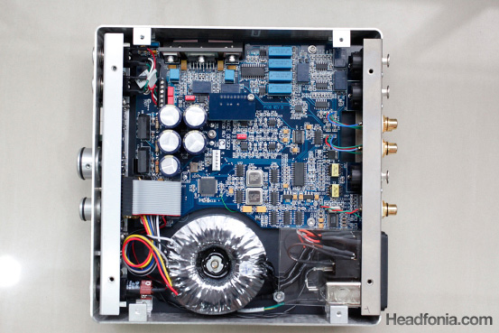
The Grace m902 DAC/Amp unit. On the right side is the input side (back panel of the amp), the right side is the output side (front panel).
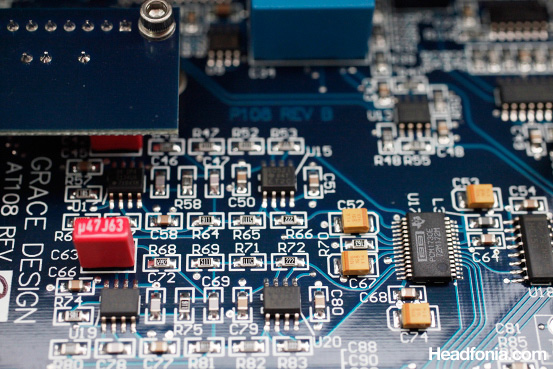
Grace m902 DAC analog section.
Here is a close up view of the DAC section. The D/A chip is a PCM1730 (the one big rectangular chip on the right side of the picture), and on the left side is the analog stage of the DAC section. Not visible in the picture is the power supply for the DAC section, the internal DAC clock circuitry, the S/PDIF and USB receivers for the digital signal.
Some manufacturers decide to scrape off the markings on the chip, making it very difficult to study the circuit, like on the Ibasso PB1 circuit below. But generally, having access to the chip codes is essential to determining how a certain circuit functions, since the chip’s datasheet will give a fairly thorough information on the function of the chips, as well as a typical implementation circuit schematic. After some time, after much exposure to the chips, you can quickly identify different chips without having to consult Google (remember how looking at headphone pictures used to be so confusing, remembering which model is which?).
While circuit complexities don’t necessarily determine sound quality, they do have quite a strong correlation. Having auditioned a very large number of DACs and Amps, bigger units usually sound better than smaller units. But remember that there is always exceptions to the rule. While this has been quite a rough overview, I hope the article can help you to be more familiar with amplifier circuits.
For more reading, you can check out the discussion thread titledPCB layout, where we have some inputs from David and Pyschaudio regarding amplifier design.


Dean_jet
I was glad you used the Dacmagic as i own one and opened it up for a look but could not work out where bits were lol
Is it sad of me to really like the internal look of the M-stage, its really neat and tidy compared to others!
Mike
You have the DacMagic too? That thing sound good doesn't it? I personally love the symmetrical layout of the Beta22 amp. 🙂
Dean_jet
Really good read!
Mike
Thanks Dean!
Dean_jet
Yeah i do like the sound but i have not really hurd any other dac accept the internal dac of my reciever. I recently bought a AudioQuest Ciniman USB cable for it which was good!
On the M-stage, the 2 big psu capasitors, does having few big ones or lots of smaller ones like on the dacmagic have any benefits?
Mike
I think that's mostly due to space constraints and layout purposes. It shouldn't matter if you have several small ones or one big one.
Dean_jet
Well I was thinking, why use lots of small ones if you could just use a few big ones, gives you more space for other things and must be cheaper?
The Beta22 amp is a hefty size, I’m surprised they made such a big box!
So I understand that separating everything is better but i don’t get why? Is it to do with interference?
I no how to solder so i was thinking of doing some building to help me learn, like a DIY amp or something that i have read about, any suggestions?
I know its off topic but I just read your first impressions of the HM-602 looks really good!
Mike
Well often a certain brand capacitor only comes at a certain size, and another reason that is also important is also the bigger a capacitor in diameter is, the taller it often gets. So, everything gets calculated into the enclosure design.
Separating the box can be for two reasons. One, to get a smaller footprint. I.e: if the Beta22 was cramped into one box, it would be one really big box. The second reason often is to place the travo away from the amp circuitry, since the travo will induce a hum when placed close to the amp.
The Cmoy amp is always a good place to start learning. You can start by reading tangensoft's cmoy tutorial (google tangensoft cmoy). Pyschaudio is making Cmoy PCBs and a bunch of us is ordering the PCB. But shipping cost can be far more expensive, and besides for learning purpose it'll probably be better to use a plain board.
The HM-602 is looking very good!
Dean_jet
Just took a quick look, very interesting, looks like a great read. Thank you.
wwenze
Two big capacitors “in the main PSU”, one for +V and one for -V
Multiple smaller ones near each individual components for “faster local power supply”, also +V and -V where applicable
Mike
Thanks wwenze. People like you should write full length articles. 🙂
David
About big vs smaller cap array:
Some designer choose to use of multiple smaller capacitors to get a smaller ESR (internal resistance).
1 unit of 10,000uF cap will be most likely would have higher ESR then 10 x 1000uF capacitor.
Think power supply like an amplifier supplying power to the load, but in this case is the circuit as the load. The lower the power supply impedance (here the cap array usually fronting) the more robust and control that the PSU have over the circuit.
Mike
Thanks David. Got anything else to share? I'm sure I missed a LOT of things on that article!
wwenze
10 x 1000uF caps also take up more physical and PCB space than a 10000uF cap from the same series, while the rated impedance (usually at 100kHz) of a 1000uF cap is roughly 3 to 5 times that of a 10000uF cap from the same series.
Then the extra PCB trace length required to connect the capacitors together negates the benefit of lower impedance for the same capacitance.
And one can mount probably two to four 10000uF caps in the same physical and PCB space required for 10 x 1000uF caps.
Mike
Thanks wwenze for the addition!
Dean_jet
What is the IC Socket/chip for on the dacmagic next to the dsp chip, I can’t get the white sticker off it!
Mike
Dean, the files are low resolution, and I can’t read it as well.
Jonathan
Hello. I can't see the pics on page 1 🙁
Mike
I will get it fixed immediately!
Mike
Everything is fixed now. Thanks for letting me know about this problem. 🙂
Jonathan
Wooohooo.. Thanks a bunch.
Qusp
i dont think you can be so general with a dac, most high quality dacs will have power supply components scattered liberally throughout and particularly local to each section, the dac chip itself will have several for what is usually several different required voltages, the clock definitely needs local regulation as do the spdif or usb input receivers . in a good layout this will be separated further into digital and analogue sections, often each with its own ground plane.
Anonymous
Thanks, Qusp.
Qusp
no problem, its a complex subject, these techniques are most often just used for dacs, its rare, but not unheard of for amplifiers. for dacs the regulators and associated decoupling caps should be as close to the supply pins as possible. some companies and indeed diyers take this to the extreme.
Anonymous
Yes, you’re right. Anyway the article is just meant as an introductory article.