


Moving on to DACs, you can have a very simple layout like the HRT Music Streamers, or something more complex like the Cambridge Audio DacMagic.
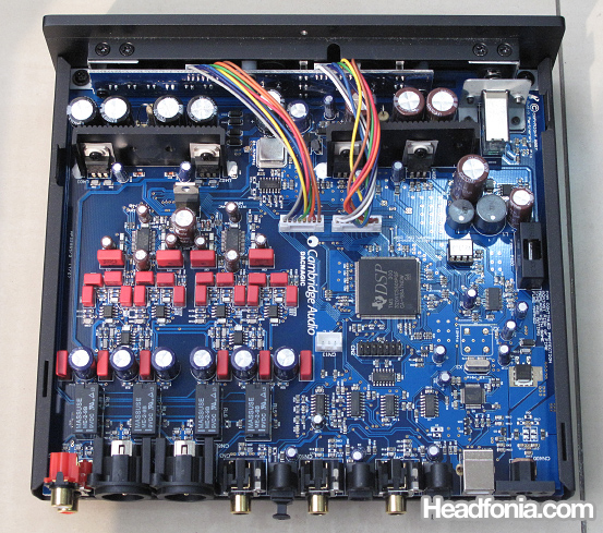
The DacMagic internals.
Notice that you don’t see any travo inside the DacMagic circuit, that’s because the DacMagic uses an external wallwart supply (albeit an AC voltage one). On the right side you see a big chip with the “DSP” marking. Doing some reading about the DacMagic will reveal that Cambridge uses a Texas Instruments DSP Chip to perform upsampling operation on the digital signal. So the circuit on the right side is most probably dedicated to that function. This is only unique on the DacMagic, and is not something that you will find on all DACs.
On the left side you see another circuit, and if you look closely, there are two chips with the marking “WM8740” written on it. A quick google check reveals that it’s a D/A chip that does the actual digital to analog conversion. Since the D/A chip requires a power supply to operate, Cambridge has put the power supply circuit right on top of the DAC sections. On the picture below you can see there are two chips with three legs, mounted on a heatsink. That is the PSU circuit for the DAC section. You can also see the two WM8740 chips on closer view right on the bottom side of the picture). If you go back to the big picture, above the heatsinks are some capacitors, and they are also a part of the PSU circuit.
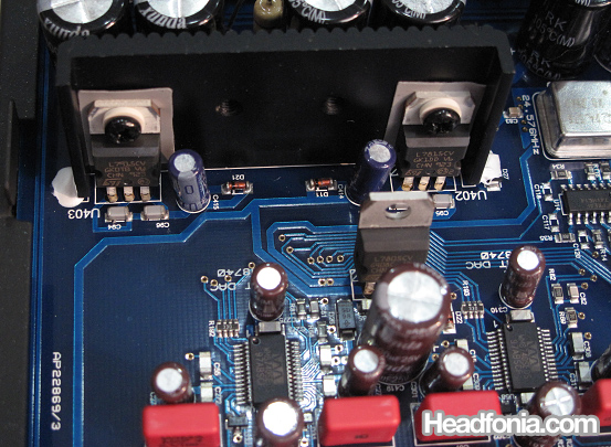
The two three-legged chips on the heatsink (top section) are power supply regulators for the DAC section. The two identical chips near the bottom with many legs are the WM8740 D/A chip.
Every DAC circuit needs an analog section to amplify the signal coming out of the DAC chip into a proper line level signal. Hence the op-amps seen on this picture. There is one small chip with OP275 written on it, and two small chips with N5532 written on them. The red cubes are the famous Wima capacitors. At the really bottom, left of the “Headfonia” watermark, is a portion of the WM8740 DAC chip. So an analog signal comes out from the WM8740 DAC chip, and is amplified by the N5532 chips, and finally into the OP275 chip. The surrounding components are the required elements for the chips to function properly. Going back to the big picture, you can see that after the DAC section, there is a row of capacitors (the red Wima blocks and the round ones) that should be the output capacitors section.
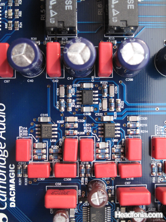
Analog stage for the DAC section. The WM8740 DAC is at the very bottom.
Before we finish with the DacMagic, please notice the PCB that’s mounted on the front panel. Without going into too much detail (and it’s way more than what I know anyway), that section is dedicated to the user interface, as the DacMagic has a digital interface for selecting input sources, digital filters, etc.
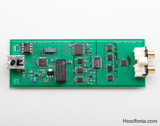
The layout for the HRT Music Streamer II+. Very logical layout. Digital signal comes in through the USB jack on the left, processed through the digital-to-analog circuitry, and out as analog signal on the right (RCA jacks).
In contrast to the DacMagic, you also have much simpler DAC unit like the HRT Music Streamer:
The HRT Music Streamer design is very simple and yet very logical. Digital signal comes in on the left side of the PCB via the USB connector (with the “OK” marking). The HRT Music Streamer uses power from the USB to operate its circuitry, so some of the signal from the USB goes to the PSU circuit, and some into the digital processing unit. The square chip with lots of pins on all four sides is the TAS1020 chip, which receives the incoming USB signal. There is one chip two-thirds down the length of the PCB, with a line going right through the middle: that is the PCM1794 chip that does the digital to analog conversion. You can google the chip codes to see what they do, normally the google result will show you a datasheet of the chip (below is a datasheet of the PCM1794 D/A chip). Then on the right side of the PCM1794 is the corresponding analog stage for the DAC and finally out to the RCA connectors as line level analog signals.
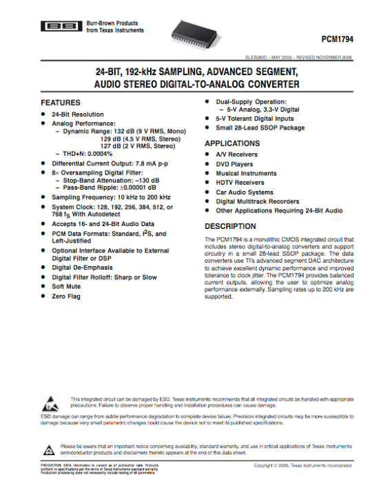
A datasheet tells you what the chip does and how to apply it correctly. This is the first page of the PCM1794 datasheet.
Next we’ll take a look at an integrated DAC/Amplifier circuit.
Dean_jet
I was glad you used the Dacmagic as i own one and opened it up for a look but could not work out where bits were lol
Is it sad of me to really like the internal look of the M-stage, its really neat and tidy compared to others!
Mike
You have the DacMagic too? That thing sound good doesn't it? I personally love the symmetrical layout of the Beta22 amp. 🙂
Dean_jet
Really good read!
Mike
Thanks Dean!
Dean_jet
Yeah i do like the sound but i have not really hurd any other dac accept the internal dac of my reciever. I recently bought a AudioQuest Ciniman USB cable for it which was good!
On the M-stage, the 2 big psu capasitors, does having few big ones or lots of smaller ones like on the dacmagic have any benefits?
Mike
I think that's mostly due to space constraints and layout purposes. It shouldn't matter if you have several small ones or one big one.
Dean_jet
Well I was thinking, why use lots of small ones if you could just use a few big ones, gives you more space for other things and must be cheaper?
The Beta22 amp is a hefty size, I’m surprised they made such a big box!
So I understand that separating everything is better but i don’t get why? Is it to do with interference?
I no how to solder so i was thinking of doing some building to help me learn, like a DIY amp or something that i have read about, any suggestions?
I know its off topic but I just read your first impressions of the HM-602 looks really good!
Mike
Well often a certain brand capacitor only comes at a certain size, and another reason that is also important is also the bigger a capacitor in diameter is, the taller it often gets. So, everything gets calculated into the enclosure design.
Separating the box can be for two reasons. One, to get a smaller footprint. I.e: if the Beta22 was cramped into one box, it would be one really big box. The second reason often is to place the travo away from the amp circuitry, since the travo will induce a hum when placed close to the amp.
The Cmoy amp is always a good place to start learning. You can start by reading tangensoft's cmoy tutorial (google tangensoft cmoy). Pyschaudio is making Cmoy PCBs and a bunch of us is ordering the PCB. But shipping cost can be far more expensive, and besides for learning purpose it'll probably be better to use a plain board.
The HM-602 is looking very good!
Dean_jet
Just took a quick look, very interesting, looks like a great read. Thank you.
wwenze
Two big capacitors “in the main PSU”, one for +V and one for -V
Multiple smaller ones near each individual components for “faster local power supply”, also +V and -V where applicable
Mike
Thanks wwenze. People like you should write full length articles. 🙂
David
About big vs smaller cap array:
Some designer choose to use of multiple smaller capacitors to get a smaller ESR (internal resistance).
1 unit of 10,000uF cap will be most likely would have higher ESR then 10 x 1000uF capacitor.
Think power supply like an amplifier supplying power to the load, but in this case is the circuit as the load. The lower the power supply impedance (here the cap array usually fronting) the more robust and control that the PSU have over the circuit.
Mike
Thanks David. Got anything else to share? I'm sure I missed a LOT of things on that article!
wwenze
10 x 1000uF caps also take up more physical and PCB space than a 10000uF cap from the same series, while the rated impedance (usually at 100kHz) of a 1000uF cap is roughly 3 to 5 times that of a 10000uF cap from the same series.
Then the extra PCB trace length required to connect the capacitors together negates the benefit of lower impedance for the same capacitance.
And one can mount probably two to four 10000uF caps in the same physical and PCB space required for 10 x 1000uF caps.
Mike
Thanks wwenze for the addition!
Dean_jet
What is the IC Socket/chip for on the dacmagic next to the dsp chip, I can’t get the white sticker off it!
Mike
Dean, the files are low resolution, and I can’t read it as well.
Jonathan
Hello. I can't see the pics on page 1 🙁
Mike
I will get it fixed immediately!
Mike
Everything is fixed now. Thanks for letting me know about this problem. 🙂
Jonathan
Wooohooo.. Thanks a bunch.
Qusp
i dont think you can be so general with a dac, most high quality dacs will have power supply components scattered liberally throughout and particularly local to each section, the dac chip itself will have several for what is usually several different required voltages, the clock definitely needs local regulation as do the spdif or usb input receivers . in a good layout this will be separated further into digital and analogue sections, often each with its own ground plane.
Anonymous
Thanks, Qusp.
Qusp
no problem, its a complex subject, these techniques are most often just used for dacs, its rare, but not unheard of for amplifiers. for dacs the regulators and associated decoupling caps should be as close to the supply pins as possible. some companies and indeed diyers take this to the extreme.
Anonymous
Yes, you’re right. Anyway the article is just meant as an introductory article.